I am sure you will agree when you read this, Phil is the right man for the job! Anyway over to you Phil.
Notwithstanding the other jobs,
part of the pre-Beach Hop tidy up plan for the Pop was to fit or replace:
·
instruments
·
electric radiator fan
·
LED tail lights
·
stereo
· keyless (starter button)
operation
Colin was
intending to just splice into the existing loom, but experience has taught me
that, when it comes to messing with bird’s nests of wiring like the Pop
currently has, it rapidly gets to the point where it is actually quicker and
easier to start again and produce an all new loom.

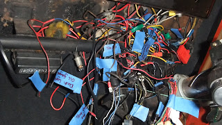
See what I mean!


Furthermore it
is safer as you can ensure all the wiring is of suitable gauge for the current draw, and is fused and routed correctly.
Given how fastidious Colin is with his
cars, I also knew he wouldn’t really be happy with the way the current (OK, bad
pun...) wiring is all exposed/hanging out under the dash.
Colin has enough on his plate as it is
with the steering and other pre- Beach Hop
tidy up work, and I wanted to help. I figured the wiring is something I
can (and want to) do to contribute.
The majority of the wiring I have done is
EFI engine swaps, and despite losing count I reckon I have done over 50 of
them. I have also wired about 10 vehicles from scratch, including Lotus 7
replicas, race and rally cars plus competition 4WDs, although I haven’t done a
full car loom for a few years. As it pans out the timing is actually pretty
good as I have got 3-4 car looms to do over the next year or so, and there are
a lot of similarities (although all the other vehicles run EFI) with the loom I
am doing for the Pop.
I prefer to wire a car by making a bespoke
wiring loom – I find the generic aftermarket wiring kits just don’t suit the
vehicles I tend to end up wiring, and hence would need a lot of modification
and additional circuits to meet the needs. I also do not think they are all
that cheap.
I am also integrating a 5-star car alarm
that not only automatically immobilises the start and run circuits, but also
controls the central locking that is likely to be fitted later. It makes far
more sense to build the alarm into the wiring loom from the outset, as it also
dictates the design of some of the circuits.
The alarm is even more critical in this
case as the car will not have a keyed ignition switch, and potentially once the
central locking is fitted the car won’t have a key at all – which means that
having some provision to get around a flat battery when the doors are still
locked might be required!
Like most of the vehicles I have wired
space in the Pop is at a premium, with my aim being to have the alarm brain,
fuses and relays packed as closely together as possible. So far I have used 7
relays and 11 fuses (with at least another 6 fuses required, and probably a
couple more relays too) so my aims of taking up not much more space than a
piece of A5 paper are looking doomed. I still expect it to have a total
footprint smaller than A4.
Given I am located in Wellington I am
making the loom up with sufficiently long wiring ‘tails’ to enable the loom to
be tailored to fit the car when I am up in Auckland in a week’s time. I have
considered the range of circuits required and tried to make allowance for all
the custom touches the wiring will need, like the ability in the future to fit
say electric windows, bigger alternator, Lexus V8... (not that I am biased).
The first circuits I tackled were the
‘run’ and ‘start’ circuits, which are fairly complicated as not only do they
need to incorporate the alarm immobiliser wiring, but I also had to figure out
a way to have the starter button only work when the ignition is turned on. I
also need to have the accessories and things like wipers drop out when the
starter motor is engaged (to reduce current draw).
The lack of a normal key switch actually
complicates things quite a bit, as the alarm automatically immobilises the run
circuit 30 seconds after the engine is turned off, and last thing I want to have
happen is the stereo not be able to be used because the alarm has cut accessory
power too. I was also mindful that to make the car more secure I needed to make
sure the alarm was immobilising the actual main power feeds, not just the small
current trigger circuits – and to achieve all this without using half a dozen
relays in the process.
It took me 6 iterations to get the drawing
right for this part of the circuit, and I found the design changed one last
time as I actually started to wire it up.
I next did the hazard lights, horn and
turn signals circuit. This is also relatively complicated as the factory hazard
light switch isn’t being used, plus a special LED compatible flasher unit is
required so the lights don’t flash too quickly given the lower overall current
draw.
The challenge here is ensuring the hazard
system works whether the car is turned on or not, but that the indicators will
not work if the car is turned off. This was achieved via a relay and a cunning
circuit. The alarm also flashes the turn signals when it is armed/disarmed, so
that circuit had to be added in too.
The headlights, wiper/washer and remaining
circuits like engine, alternator and instruments are much more standard and
will be best tackled when I am in Auckland.
Until then, here is what the ready to go loom looks like so far.

And here are a few of my scratchings so you can see just what is involved in sorting through it all.
Phil


Until then, here is what the ready to go loom looks like so far.

And here are a few of my scratchings so you can see just what is involved in sorting through it all.
Phil


Sounds like Phil is someone that I could learn a lot from and his middle name should be 'Mr. Electricy'. Looks like your car is going to have one nice upgrade to the wiring very soon and a big piece of mind as well.
ReplyDelete